ER diagram-
- ER diagram or Entity Relationship diagram is a conceptual model that gives the graphical representation of the logical structure of the database.
- It shows all the constraints and relationships that exist among the different components.
Components of ER diagram-
An ER diagram is mainly composed of following three components-
- Entity Sets
- Attributes
- Relationship Set
Example-
Consider the following Student table-
| Roll_no | Name | Age |
| 1 | Akshay | 20 |
| 2 | Rahul | 19 |
| 3 | Pooja | 20 |
| 4 | Aarti | 19 |
This complete table is referred to as "Student Entity Set" and each row represents an "entity".
Representation as ER Diagram-
The above table may be represented as ER diagram as-
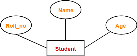
Here,
- Roll_no is a primary key that can identify each entity uniquely.
- Thus, by using student's roll number, a student can be identified uniquely.
ER Diagram Symbols-
An ER diagram is composed of several components and each component in ER diagram is represented using a specific symbol.
ER diagram symbols are discussed below-
1. For Entity Sets-
An entity set is a set of same type of entities.
An entity refers to any object having-
- Either a physical existence such as a particular person, office, house or car.
- Or a conceptual existence such as a school or a company.
An entity set may be of the following two types-
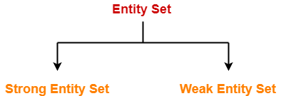
- Strong entity set
- Weak entity set
1. Strong Entity Set-
- A strong entity set possess its own primary key.
- It is represented using a single rectangle.
2. Weak Entity Set-
- A weak entity set do not possess its own primary key.
- It is represented using a double rectangle.

Read more- Entity Sets in DBMS
2. For Relationship Sets-
- Relationship defines an association among several entities.
- A relationship set is a set of same type of relationships.
A relationship set may be of the following two types-

- Strong relationship set
- Weak relationship set
1. Strong Relationship Set-
- A strong relationship exists between two strong entity sets.
- It is represented using a diamond symbol.
2. Weak Relationship Set-
- A weak or identifying relationship exists between the strong and weak entity set.
- It is represented using a double diamond symbol.

Read more- Relationship Sets in DBMS
3. For Attributes-
- Attributes are the properties which describes the entities of an entity set.
- There are several types of attributes.
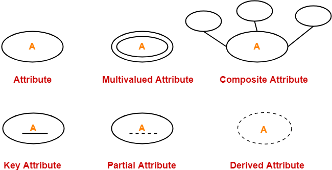
Read more- Attributes in ER Diagram
4. For Participation Constraints-
Participation constraint defines the least number of relationship instances in which an entity has to necessarily participate.
There are two types of participation constraints-

- Partial participation
- Total participation
1. Partial Participation-
Partial participation is represented using a single line between the entity set and relationship set.
2. Total Participation-
Total participation is represented using a double line between the entity set and relationship set.

Read more- Participation Constraints in DBMS
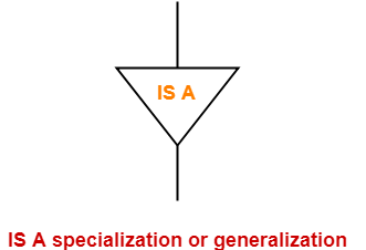
5. For Specialization and Generalization-
- Generalization is a process of forming a generalized super class by extracting the common characteristics from two or more classes.
- Specialization is a reverse process of generalization where a super class is divided into sub classes by assigning the specific characteristics of sub classes to them.
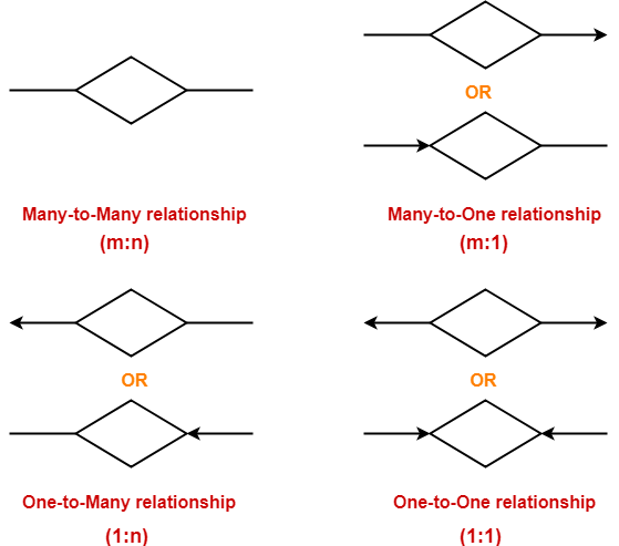
6. For Cardinality Constraints / Ratios-
Cardinality constraint defines the maximum number of relationship instances in which an entity can participate.
There are 4 types of cardinality ratios-
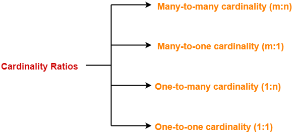
- Many-to-many cardinality (m:n)
- Many-to-one cardinality (m:1)
- One-to-many cardinality (1:n)
- One-to-one cardinality (1:1)
Read more- Cardinality Ratios in DBMS
Next Article- Entity Sets in DBMS
Get more notes and other study material of Database Management System (DBMS).
Watch video lectures by visiting our YouTube channel LearnVidFun.
Summary

Article Name
ER Diagrams | ER Diagram Symbols
Description
ER diagram is a conceptual model that gives the graphical representation of the logical structure of the database. ER Diagram Symbols are used to represent each component of ER Diagram.
Author
Akshay Singhal
Publisher Name
Gate Vidyalay
Publisher Logo

Source: https://www.gatevidyalay.com/er-diagrams/
Posted by: dionnaprosonice0193527.blogspot.com

0 Comments